Monthly Archives: November 2013

Film Back 101

WHAT IS FILM BACK AND WHY DO I NEED TO KNOW?
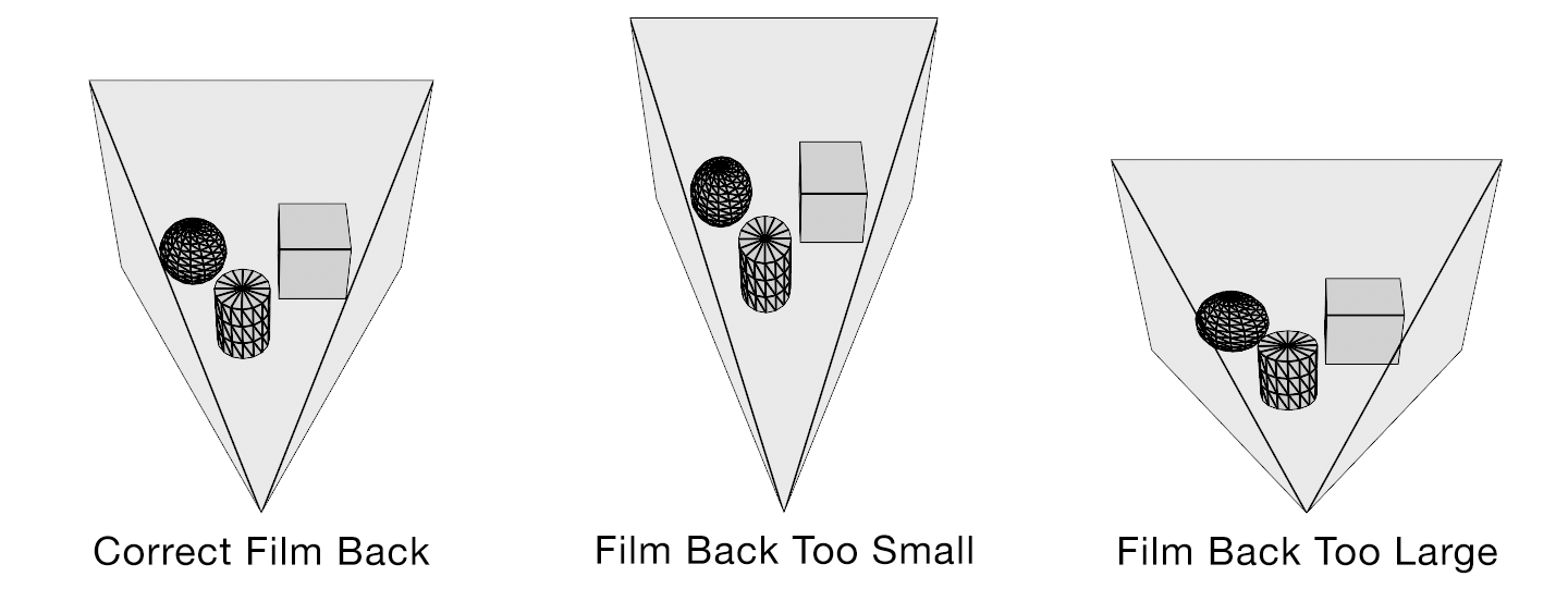
“Film back” is common terminology for the dimensions of a film frame’s or electronic sensor’s imaging area. Focal length is the optical magnification power of a lens. The field of view (FOV) (aka angle of view or viewing frustum angle) will be different on cameras with the same film back sizes using lenses of different focal lengths. The FOV will also be different if the cameras use lenses with the same focal lengths, but have different film back sizes. FOV is determined by the relationship between film back and focal length.

CropFactorGIF

In the discipline of 3D camera tracking the best camera solves are generated when the artist inputs the actual lens focal length and camera film back size used. With these two variables the software can accurately calculate the FOV of a recorded frame. If you only know one variable (or neither) the software will calculate an inaccurate solve. Leaving the artist to do a lot of time consuming guess work.

The focal length is generally easy to obtain. It is printed on the barrel of the lens and is normally written down in logs by a camera assistant. Focal length is usually also collected by a visual effects department member if they are present on set. The film back size is not always as easy to obtain. When images are acquired on film the film back size is determined by the film format being used. There are a limited number of acquisition film formats and they are standardized. Digital cameras do not use standardized sensor sizes. The size of a sensor, and more importantly what portion of it is used to record an image, is rarely published by camera manufacturers. When manufacturers do describe the size of their sensors it is usually in comparison to a film format, not the exact dimensions. Some cameras also change the area of their sensor that is used when recording different resolutions. This change is generally referred to as crop factor. Those digital cameras have different effective film back sizes for different formats and this must be accounted for when solving a camera track.

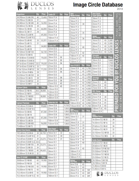
Lens Image Circle and Sensor Imaging Area
Autodesk Maya Camera Angle of View
Panavision Sensor Size & Field of View
RED, Digital and Film Format Size Chart
ARRI ALEXA XT Sensor Areas
Red MX Crop Factors

Field of view describes how much of the 3D scene a virtual camera sees. You must know the focal length and film back size so that the correct field of view can be calculated. With the correct field of view a tracked cube in your footage will generate a rectilinear point cloud of a cube in your 3D scene. Exactly matching the cube’s real world proportions. With the wrong field of view the cube will be squashed or stretched. Therefore, not an accurate 3D reconstruction of the photographed object.

fov

HOW DO SOFTWARE PACKAGES EXCHANGE CAMERA DATA?
Most software packages exchange camera information as field of view (FOV). Expressed as a horizontal (most common), vertical or diagonal angle.

WHERE DO I FIND CAMERA SETTINGS / PROPERTIES / ATTRIBUTES IN MY SOFTWARE?
3D Equalizer

SynthEyes
Shot > Edit Shot “Back Plate”

Boujou
Setup > Edit Camera > Advanced “Filmback Width/Height”

PFTrack
https://vimeo.com/channels/pftrack/85934502

Maya
Camera Attribute Editor

3ds Max
Aperture Width
http://www.designimage.co.uk/3dsmax_filmback/

Softimage
Camera Property Editor

Houdini
Camera Object Parameters
Match Houdini camera lenses to the real world

Modo
Camera Item

Cinema 4D
3D Camera Properties
http://www.maxon.net/support/documentation.html

Lightwave
http://forums.newtek.com/showthread.php?87642-Film-Back
Camera Properties
Advanced Camera

Blender
Camera
http://blenderartists.org/forum/archive/index.php/t-104137.html

Nuke
Camera
CameraTracker
Camera Film Back Presets

After Effects
Camera Settings
Virtual Cinematography in After Effects

Fusion
Camera 3D, Aperture (page 9)

Flame
3D Camera Parameters

Lens Distortion Workflow

ldw

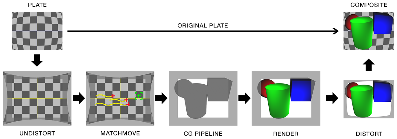
1. original plate
2. remove lens distortion (undistort plate)*
3. camera tracking/matchmove
4. cg pipeline (undistorted)
5. render cg with overscan (undistorted)**
6. distort cg render
7. composite over original plate

* Step 2 assumes a lens distortion grid was photographed or lens mapping data was acquired. Step 2 is often part of step 3. Camera tracking software can calculate lens distortion from most plates.

** Step 5 is required when undistorting barrel distortion. If overscan is not rendered the edges of the frame will be cropped when distortion is applied.


Wikipedia: Distortion (Optics)
SynthEyes Lens Distortion Tutorials
SynthEyes Lens Distortion White Paper
SynthEyes Lens Distortion and Anamorphic Padding White Paper
3D Equalizer: Lens Distortion Model
3D Equalizer: Lens Distortion in 3DE4
3DEqualizer4 R4 [advanced] – Lens Distortion Pipeline / Export Distortion Data to Nuke

Rolling Shutter Workflow

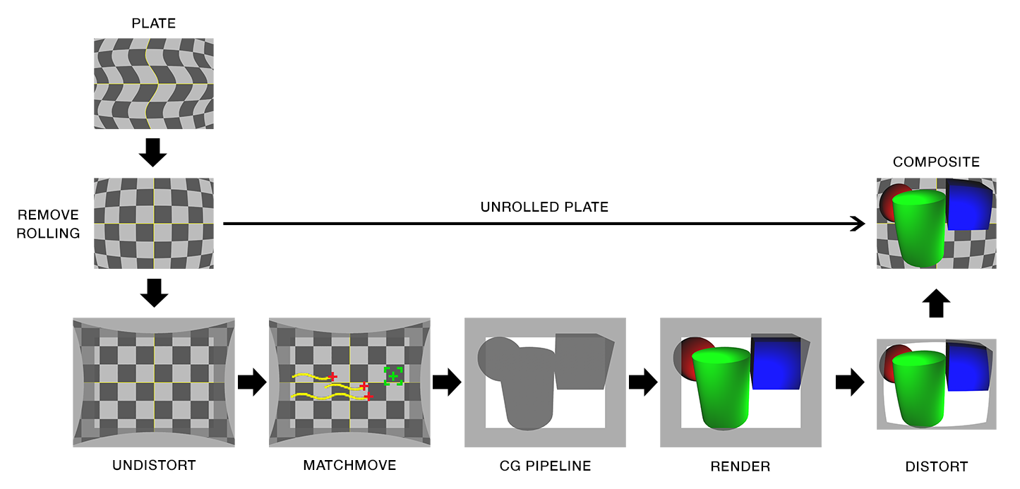
There are two workflows for handling plates with rolling shutter artifacts:

  • The first workflow is to remove the artifacts from the shot. In this scenario the final composite uses the corrected plate.
  • The second workflow is to add rolling shutter to the CG to match the plate. In this scenario the final composite uses the original uncorrected plate.


WORKFLOW 1
rswb

1. original plate
2. remove rolling shutter
3. remove lens distortion (undistort plate)*
4. camera tracking/matchmove
5. cg pipeline (undistorted)
6. render cg with overscan (undistorted)**
7. distort cg render
8. composite over unrolled plate

* Step 3 assumes a lens distortion grid was photographed or lens mapping data was acquired. Step 3 is often part of step 4. Camera tracking software can calculate lens distortion from most plates.

** Step 6 is required when undistorting barrel distortion. If overscan is not rendered the edges of the frame will be cropped when distortion is applied.


WORKFLOW 2
rsw

1. original plate
2. remove rolling shutter
3. remove lens distortion (undistort plate)*
4. camera tracking/matchmove
5. cg pipeline (undistorted)
6. render cg with overscan (undistorted)**
7. distort cg render
8. add rolling shutter
9. composite over original plate

* Step 3 assumes a lens distortion grid was photographed or lens mapping data was acquired. Step 3 is often part of step 4. Camera tracking software can calculate lens distortion from most plates.

** Step 6 is required when undistorting barrel distortion. If overscan is not rendered the edges of the frame will be cropped when distortion is applied.


Wikipedia: Rolling Shutter
RED – Learn: Global and Rolling Shutters
RED – Learn: Temporal Aliasing with Cinema
RED – RED MOTION
Tessive: Time Filter
Tessive: Time Filter Technical Explanation
DIY Photography: Everything You Ever Wanted To Know About Rolling Shutter
Rolling Shutter on CMOS
Adobe After Effects: Rolling Shutter Repair
Adobe Premiere Pro: Rolling Shutter Repair
SynthEyes Rolling Shutter Tutorials
3DEqualizer4 [advanced] – Rolling Shutter
3D Equalizer: Rolling Shutter Correction in 3DE4
The Foundry: Rolling Shutter (Defunct)

Anamorphic Workflow

Squeeze

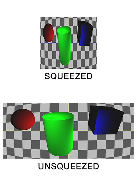
Anamorphic lenses allow a widescreen picture to fit in a normal frame without letterboxing. This is accomplished by optically squeezing the image horizontally. While technically unnecessary today, filmmakers continue to use anamorphic lenses for their cinematic aesthetic.
Anamorphic images stay squeezed throughout the entire visual effects pipeline. For convenience they are displayed as unsqueezed in most software packages, but this is only superficial.
The squeezing is defined by the image’s pixel aspect ratio. The standard pixel aspect ratio is 1.0 (square). The most common anamorphic pixel aspect ratio is 2.0. For anamorphic shots the virtual camera’s film back width is multiplied by the pixel aspect ratio. This is usually around double, as in the case of CinemaScope (2.0).

CinemaScope 35 mm film (2K scan):
Squeezed (actual) = 1828 x 1556
Unsqueezed (display) = 3656 x 1556
Physical film back = 21.936 mm x 18.672 mm
Virtual film back = 43.872 mm x 18.672 mm


Anamorphic Flowchart:

(click to enlarge)

Anamorphic Workflow Diagram

1. original plate
2. remove lens distortion (undistort plate)*
3. camera tracking/matchmove
4. cg pipeline (undistorted)
5. render cg with overscan (undistorted)**
6. distort cg render
7. composite over original plate

* Step 2 assumes a lens distortion grid was photographed or lens mapping data was acquired. Step 2 is often part of step 3. Camera tracking software can calculate lens distortion from most plates.

** Step 5 is required when undistorting barrel distortion. If overscan is not rendered the edges of the frame will be cropped when distortion is applied.


Wikipedia: Anamorphosis
Wikipedia: Anamorphic Format
Wikipedia: Pixel Aspect Ratio
RED – Learn: Understanding Anamorphic Lenses
ARRI ALEXA Anamorphic De-squeeze White Paper
SynthEyes Lens Distortion and Anamorphic Padding White Paper
3DEqualizer4 R3 [exercise] Anamorphic Distortion and Lens Breathing
http://www.metrics.co.uk/support/solution_view.php?id=1563
http://www.metrics.co.uk/support/solution_view.php?id=1528
https://www.ssontech.com/content/lensflo.html


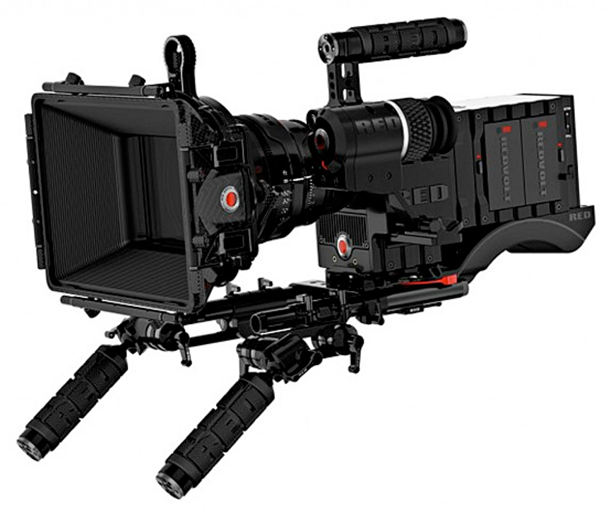
RED WEAPON DRAGON 6K S35

Red Epic


Sensor Type:
CMOS (RED WEAPON DRAGON 6K S35)

Shutter:
Rolling

Sensor Imaging Area:
NOTE: This camera crops the sensor to change formats. The imaging area of the sensor is different depending on which format a take was acquired in.
6144 x 3160      6K FF         30.70 mm x 15.80 mm (1.208 in x 0.622 in)
6144 x 3072      6K 2:1        30.70 mm x 15.35 mm (1.208 in x 0.604 in)
6144 x 2592      6K WS        30.70 mm x 12.95 mm (1.208 in x 0.509 in)
5568 x 3132      6K HD        27.82 mm x 15.65 mm (1.095 in x 0.616 in)

5600 x 2960      5.5K FF       27.98 mm x 14.79 mm (1.101 in x 0.582 in)
5600 x 2800      5.5K 2:1     27.98 mm x 13.99 mm (1.101 in x 0.550 in)
5600 x 2360      5.5K WS     27.98 mm x 11.79 mm (1.101 in x 0.464 in)
5280 x 2960      5.5K HD     26.38 mm x 14.79 mm (1.038 in x 0.582 in)

5120 x 2700      5K FF         25.58 mm x 13.49 mm (1.007 in x 0.531 in)
5120 x 2560      5K 2:1        25.58 mm x 12.79 mm (1.007 in x 0.503 in)
5120 x 2160      5K WS        25.58 mm x 10.79 mm (1.007 in x 0.424 in)
4800 x 2700      5K HD        23.98 mm x 13.49 mm (0.944 in x 0.531 in)

4608 x 2432      4.5K FF       23.04 mm x 12.16 mm (0.907 in x 0.479 in)
4608 x 2304      4.5K 2:1     23.04 mm x 11.52 mm (0.907 in x 0.453 in)
4608 x 1944      4.5K WS     23.04 mm x 9.72 mm (0.907 in x 0.383 in)
4320 x 2432      4.5K HD     21.60 mm x 12.16 mm (0.850 in x 0.479 in)

4096 x 2160      4K FF          20.47 mm x 10.79 mm (0.870 in x 0.459 in)
4096 x 2048      4K 2:1        20.47 mm x 10.23 mm (0.870 in x 0.435 in)
4096 x 1728      4K WS        20.47 mm x 8.63 mm (0.870 in x 0.362 in)
3840 x 2160      4K HD        19.19 mm x 10.79 mm (0.816 in x 0.459 in)

3072 x 1620      3K              16.59 mm x 8.75 mm (0.653 in x 0.344 in)
2880 x 1620      3K HD       15.55 mm x 8.75 mm (0.000 in x 0.344 in)
3072 x 1536      3K 2:1       16.59 mm x 8.29 mm (0.653 in x 0.326 in)
3072 x 1280      3K WS       16.59 mm x 6.91 mm (0.653 in x 0.272 in)

2048 x 1080      2K              11.06 mm x 5.83 mm (0.435 in x 0.229 in)
1920 x 1080      2K HD       10.37 mm x 5.83 mm (0.408 in x 0.229 in)
2048 x 1024      2K 2:1       11.06 mm x 5.54 mm (0.435 in x 0.218 in)
2048 x 854        2K WS       11.06 mm x 4.61 mm (0.435 in x 0.181 in)

1280 x 720        1K HD       6.91 mm x 3.88 mm (0.272 in x 0.153 in)
1280 x 480        1K WS       6.91 mm x 2.59 mm (0.272 in x 0.102 in)

Image Resolution:
6144 x 3160      6K FF – Full Frame (1.94:1)
6144 x 3072      6K 2:1 – (2:1)
6144 x 2592      6K WS – Wide Screen (2.37:1)
5568 x 3132      6K HD – High Definition (1.78:1)

5600 x 2960      5.5K FF
5600 x 2800      5.5K 2:1
5600 x 2360      5.5K WS
5280 x 2960      5.5K HD

5120 x 2700      5K FF
5120 x 2560      5K 2:1
5120 x 2160      5K WS
4800 x 2700      5K HD

4608 x 2432      4.5K FF
4608 x 2304      4.5K 2:1
4608 x 1944      4.5K WS
4320 x 2432      4.5K HD

4096 x 2160      4K FF
4096 x 2048      4K 2:1
4096 x 1728      4K WS
3840 x 2160      4K HD

3072 x 1620      3K
2880 x 1620      3K HD
3072 x 1536      3K 2:1
3072 x 1280      3K WS

2048 x 1080      2K
1920 x 1080      2K HD
2048 x 1024      2K 2:1
2048 x 854        2K WS

1280 x 720        1K HD
1280 x 480        1K WS

Output Type:
16-bit RAW REDCODE R3D
12-bit RAW REDCODE R3D

See Also: RED Epic Dragon Formats

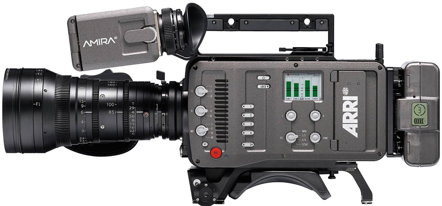
ARRI AMIRA

ARRI-AMIRA


Sensor Type:
CMOS (ALEV III)

Shutter:
Rolling

Sensor Dimensions:
NOTE: This camera crops the sensor to change formats. The imaging area of the sensor is different depending on which format a take was acquired in.
3840 x 2160       4K UHD                               26.40 mm x 14.85 mm (1.039 in x 0.585 in)
3424 x 2202       3.4K Open Gate                 28.25 mm x 18.17 mm (1.112 in x 0.715 in)
3200 x 1800       3.2K                                     26.40 mm x 14.85 mm (1.039 in x 0.585 in)
2880 x 1620       2.8K                                     23.76 mm x 17.82 mm (0.935 in x 0.702 in)
2048 x 1152       2K                                         23.66 mm x 13.30 mm (0.932 in x 0.524 in)
1920 x 1080       HD                                       23.76 mm x 13.37 mm (0.935 in x 0.526 in)
1920 x 1080       S16 HD                               13.2 mm x 7.425 mm (0.520 in x 0.292 in)

Image Resolution:
3840 x 2160
3424 x 2202
3200 x 1800
2880 x 1620
2048 x 1152
1920 x 1080

Output Type:
12-bit ARRIRAW
10-bit 1080PsF 4:4:4 RGB (HD-SDI)
10-bit 1080PsF 4:2:2 YCbCr (HD-SDI)
12-bit 2K Apple ProRes
10-bit HD Apple ProRes