Category Archives: workflow

Motion Control

Motion control is the use of robotic camera equipment to create programmable, precise and repeatable camera moves. Many professional motion control service providers use custom rigs, some use commercially produced rigs such and the Milo. Lately, companies such as Bot & Dolly, The Marmalade and Mark Roberts Motion Control have adapted robotic arms normally used in manufacturing.

You can use motion control data as a seed or guide path for your virtual camera solve. The data from motion control rigs is the instructions, not a record of the actual movement. Therefore, the bumps and jitter present in the plate are not present in the data. This means that footage shot with a motion control system must still be tracked. Lightcraft Technology’s Previzion records the actual movement so it’s data has the potential to be more accurate than a rig’s.

moco_header

Motion control data is primarily distributed as an ASCII table. Each row represents a frame and each column represents an axis of motion. The motion control system should be genlocked with the camera. After importing into a 3D package the motion control data will need to be conformed. The first step is synchronizing with the plate. This is usually done by using a bloop light recorded in the plate. The bloop frame should be noted in your delivered data. The path will then need to be oriented and scaled to match the virtual set. Some motion control systems have tools to assist with this. Some do not. The two most common motion control data formats are Kuper and Flair.

Motion control data can come from the following sources:

  • Traditional motion control rig with a crane and dolly
  • Motion control head
  • Lightcraft Technology’s Previzion and Airtrack
  • Lens Data System (LDS)

Pacific Motion Control: Kuper CG Resources
Pacific Motion Control: Technodolly CG Resources
FLAIR Motion Control System
Camera Control

Survey, LIDAR and Reference Frames

Survey data can be used to increase the accuracy of camera solves, solve cameras that have zero parallax and solve different cameras in a matching scene layout. Survey data can be obtained by traditional surveying with a Total Station, scanning with LIDAR or shooting reference frames for photogrammetry.

Camera tracking software normally works by 2D tracking features in an image sequence. Using a photogrammetry algorithm it then estimates the 3D coordinates of these features. The camera is then solved based on the relationship of these coordinates. Using survey data is different. Instead of having the algorithm estimate the position of a 3D coordinate you simply tell the software where it is. If your survey data is accurate it will provide you with a better camera solve than estimation alone. Survey data and software estimation techniques can be combined.

bremen

Total Station
Survey data collected by a skilled surveyor with a Total Station is extremely accurate. However, this data is less convenient to correlate with production plates because it is a low density point cloud.

LIDAR
LIDAR scans provide excellent accuracy and a high density point cloud. In order to maximize usefulness in a visual effects pipeline the point cloud should be meshed.

Photogrammetry
Photogrammetry can be used to create a low or medium density point cloud of a set. This point cloud can be meshed. A large number of photographs are required and photogrammetry is generally less accurate than LIDAR or Total Stations.

Reference Frames
Reference frames are used to give the camera solving algorithm more parallax. Reference frames are photographs of the set taken from angles different from the plate camera. These photos must have overlapping coverage of the features being 2D tracked. They can include DSLR photos, videos and witness cameras. Reference images can also be taken of specific objects or props to assist in object tracking.

Film Back 101

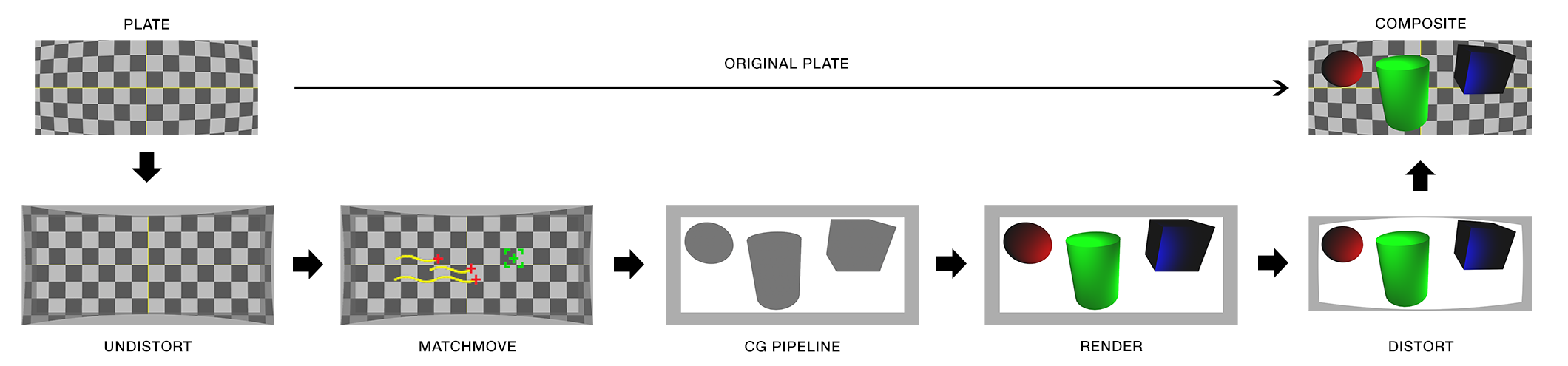
WHAT IS FILM BACK AND WHY DO I NEED TO KNOW?
“Film back” is common terminology for the dimensions of a film frame’s or electronic sensor’s imaging area. Focal length is the optical magnification power of a lens. The field of view (FOV) (aka angle of view or viewing frustum angle) will be different on cameras with the same film back sizes using lenses of different focal lengths. The FOV will also be different if the cameras use lenses with the same focal lengths, but have different film back sizes. FOV is determined by the relationship between film back and focal length.

CropFactorGIF

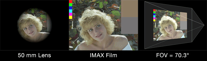
In the discipline of 3D camera tracking the best camera solves are generated when the artist inputs the actual lens focal length and camera film back size used. With these two variables the software can accurately calculate the FOV of a recorded frame. If you only know one variable (or neither) the software will calculate an inaccurate solve. Leaving the artist to do a lot of time consuming guess work.

The focal length is generally easy to obtain. It is printed on the barrel of the lens and is normally written down in logs by a camera assistant. Focal length is usually also collected by a visual effects department member if they are present on set. The film back size is not always as easy to obtain. When images are acquired on film the film back size is determined by the film format being used. There are a limited number of acquisition film formats and they are standardized. Digital cameras do not use standardized sensor sizes. The size of a sensor, and more importantly what portion of it is used to record an image, is rarely published by camera manufacturers. When manufacturers do describe the size of their sensors it is usually in comparison to a film format, not the exact dimensions. Some cameras also change the area of their sensor that is used when recording different resolutions. This change is generally referred to as crop factor. Those digital cameras have different effective film back sizes for different formats and this must be accounted for when solving a camera track.

Lens Image Circle and Sensor Imaging Area
Autodesk Maya Camera Angle of View
Panavision Sensor Size & Field of View
RED, Digital and Film Format Size Chart
ARRI ALEXA XT Sensor Areas
Red MX Crop Factors

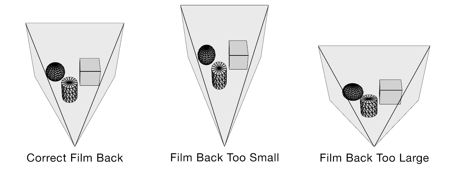
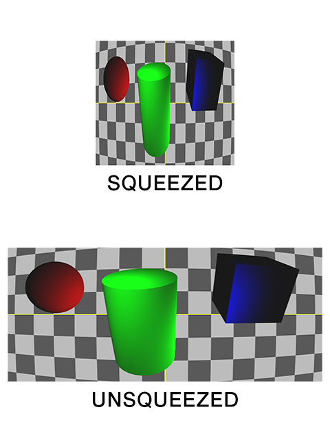
Field of view describes how much of the 3D scene a virtual camera sees. You must know the focal length and film back size so that the correct field of view can be calculated. With the correct field of view a tracked cube in your footage will generate a rectilinear point cloud of a cube in your 3D scene. Exactly matching the cube’s real world proportions. With the wrong field of view the cube will be squashed or stretched. Therefore, not an accurate 3D reconstruction of the photographed object.

fov

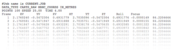
HOW DO SOFTWARE PACKAGES EXCHANGE CAMERA DATA?
Most software packages exchange camera information as field of view (FOV). Expressed as a horizontal (most common), vertical or diagonal angle.

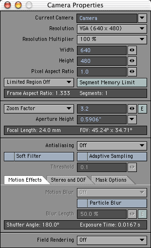
WHERE DO I FIND CAMERA SETTINGS / PROPERTIES / ATTRIBUTES IN MY SOFTWARE?
3D Equalizer

SynthEyes
Shot > Edit Shot “Back Plate”

Boujou
Setup > Edit Camera > Advanced “Filmback Width/Height”

PFTrack
https://vimeo.com/channels/pftrack/85934502

Maya
Camera Attribute Editor

3ds Max
Aperture Width
http://www.designimage.co.uk/3dsmax_filmback/

Softimage
Camera Property Editor

Houdini
Camera Object Parameters
Match Houdini camera lenses to the real world

Modo
Camera Item

Cinema 4D
3D Camera Properties
http://www.maxon.net/support/documentation.html

Lightwave
http://forums.newtek.com/showthread.php?87642-Film-Back
Camera Properties
Advanced Camera

Blender
Camera
http://blenderartists.org/forum/archive/index.php/t-104137.html

Nuke
Camera
CameraTracker
Camera Film Back Presets

After Effects
Camera Settings
Virtual Cinematography in After Effects

Fusion
Camera 3D, Aperture (page 9)

Flame
3D Camera Parameters

Lens Distortion Workflow

ldw

1. original plate
2. remove lens distortion (undistort plate)*
3. camera tracking/matchmove
4. cg pipeline (undistorted)
5. render cg with overscan (undistorted)**
6. distort cg render
7. composite over original plate

* Step 2 assumes a lens distortion grid was photographed or lens mapping data was acquired. Step 2 is often part of step 3. Camera tracking software can calculate lens distortion from most plates.

** Step 5 is required when undistorting barrel distortion. If overscan is not rendered the edges of the frame will be cropped when distortion is applied.


Wikipedia: Distortion (Optics)
SynthEyes Lens Distortion Tutorials
SynthEyes Lens Distortion White Paper
SynthEyes Lens Distortion and Anamorphic Padding White Paper
3D Equalizer: Lens Distortion Model
3D Equalizer: Lens Distortion in 3DE4
3DEqualizer4 R4 [advanced] – Lens Distortion Pipeline / Export Distortion Data to Nuke

Rolling Shutter Workflow

There are two workflows for handling plates with rolling shutter artifacts:

  • The first workflow is to remove the artifacts from the shot. In this scenario the final composite uses the corrected plate.
  • The second workflow is to add rolling shutter to the CG to match the plate. In this scenario the final composite uses the original uncorrected plate.


WORKFLOW 1
rswb

1. original plate
2. remove rolling shutter
3. remove lens distortion (undistort plate)*
4. camera tracking/matchmove
5. cg pipeline (undistorted)
6. render cg with overscan (undistorted)**
7. distort cg render
8. composite over unrolled plate

* Step 3 assumes a lens distortion grid was photographed or lens mapping data was acquired. Step 3 is often part of step 4. Camera tracking software can calculate lens distortion from most plates.

** Step 6 is required when undistorting barrel distortion. If overscan is not rendered the edges of the frame will be cropped when distortion is applied.


WORKFLOW 2
rsw

1. original plate
2. remove rolling shutter
3. remove lens distortion (undistort plate)*
4. camera tracking/matchmove
5. cg pipeline (undistorted)
6. render cg with overscan (undistorted)**
7. distort cg render
8. add rolling shutter
9. composite over original plate

* Step 3 assumes a lens distortion grid was photographed or lens mapping data was acquired. Step 3 is often part of step 4. Camera tracking software can calculate lens distortion from most plates.

** Step 6 is required when undistorting barrel distortion. If overscan is not rendered the edges of the frame will be cropped when distortion is applied.


Wikipedia: Rolling Shutter
RED – Learn: Global and Rolling Shutters
RED – Learn: Temporal Aliasing with Cinema
RED – RED MOTION
Tessive: Time Filter
Tessive: Time Filter Technical Explanation
DIY Photography: Everything You Ever Wanted To Know About Rolling Shutter
Rolling Shutter on CMOS
Adobe After Effects: Rolling Shutter Repair
Adobe Premiere Pro: Rolling Shutter Repair
SynthEyes Rolling Shutter Tutorials
3DEqualizer4 [advanced] – Rolling Shutter
3D Equalizer: Rolling Shutter Correction in 3DE4
The Foundry: Rolling Shutter (Defunct)

Anamorphic Workflow

Squeeze

Anamorphic lenses allow a widescreen picture to fit in a normal frame without letterboxing. This is accomplished by optically squeezing the image horizontally. While technically unnecessary today, filmmakers continue to use anamorphic lenses for their cinematic aesthetic.
Anamorphic images stay squeezed throughout the entire visual effects pipeline. For convenience they are displayed as unsqueezed in most software packages, but this is only superficial.
The squeezing is defined by the image’s pixel aspect ratio. The standard pixel aspect ratio is 1.0 (square). The most common anamorphic pixel aspect ratio is 2.0. For anamorphic shots the virtual camera’s film back width is multiplied by the pixel aspect ratio. This is usually around double, as in the case of CinemaScope (2.0).

CinemaScope 35 mm film (2K scan):
Squeezed (actual) = 1828 x 1556
Unsqueezed (display) = 3656 x 1556
Physical film back = 21.936 mm x 18.672 mm
Virtual film back = 43.872 mm x 18.672 mm


Anamorphic Flowchart:

(click to enlarge)

Anamorphic Workflow Diagram

1. original plate
2. remove lens distortion (undistort plate)*
3. camera tracking/matchmove
4. cg pipeline (undistorted)
5. render cg with overscan (undistorted)**
6. distort cg render
7. composite over original plate

* Step 2 assumes a lens distortion grid was photographed or lens mapping data was acquired. Step 2 is often part of step 3. Camera tracking software can calculate lens distortion from most plates.

** Step 5 is required when undistorting barrel distortion. If overscan is not rendered the edges of the frame will be cropped when distortion is applied.


Wikipedia: Anamorphosis
Wikipedia: Anamorphic Format
Wikipedia: Pixel Aspect Ratio
RED – Learn: Understanding Anamorphic Lenses
ARRI ALEXA Anamorphic De-squeeze White Paper
SynthEyes Lens Distortion and Anamorphic Padding White Paper
3DEqualizer4 R3 [exercise] Anamorphic Distortion and Lens Breathing
http://www.metrics.co.uk/support/solution_view.php?id=1563
http://www.metrics.co.uk/support/solution_view.php?id=1528
https://www.ssontech.com/content/lensflo.html